|
|
|
So far I have the pictures in place, just click on the thumbnail for hi-res pics. This burner is made form 1-1/2" pipe fittings. The ball is a 1-1/4" brass plated drawer pull I bought at home depot for about $1.60. The burner tube itself is a 12" long nipple with a standard "T" fitting and plug. I'll clean this page up later, right now, I just want to get my pics posted :P

Here's the parts for the burner tube all laid out. and
our QA inspector checking things out "Is it all up to specs, Athena?"

And here's the assembled burner tube

36 inches of 1/4" copper tubing that will become the preheater coil
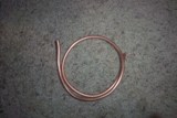
A soft bend put into the coil to help prevent kinking when it's rolled around
the soda can.
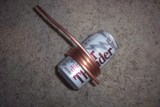
The final coil slowly rolled around the soda can to form it to the right size(close but not touching).

The preheater tube installed.

I solved the problem of making the fuel line stationary by bolting a copper plate to
pipe to give me something to solder to, notice the one on the back too? we'll get to
that one later. The fuel line needs to be stationary as it's the only thing holding the
preheater coil in position and keeping it from touching the burner tube so the fuel doesn't
vaporize in the fuel line causing carbon fouling. Besides, I kinda
like the warhammer 40K look.
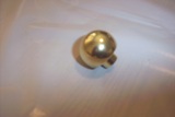
Here's where the magic of the babington burner happens, the ball. So far untouched by a drill.
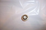
The back of the ball, drilled out. The ball was drilled out with a 3/16" bit untill the front of the
ball bulged, then a 1/4" bit was drilled 1/2" in to hold the pipe.
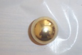
The front of the ball. You can't see it in the pic, but there is a 0.01" hole drilled
in there. I tried to get the camera closer but it just got blurry. I guess someday
I need to get a better camera.
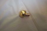
The ball soldered to it's mount which is just a compression fitting compressed onto a
piece of tubing. Notice that the back of the ball is flush with the fitting.

Here's the ball mounted in place and ready to atomize the fuel while mixing air into it.
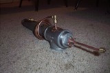
Remember that solder plate in the back I said we would get to? Here it is holding the
air tube in place, the tube goes through the plug and screws into the back of the ball
providing atomizing pressure and combustion air.
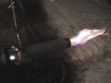
The light at the end of the tunnel! Burning diesel, still working the bugs out for WVO (Waste Vegetable Oil) to burn
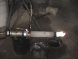
The bugs are worked out and you get a little different flame when your burning WVO.
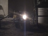
Ok here it is, the ultimate pic, straight down the barrel. I'll get one of these
in daylight too.

Babington Burner or Orcish Fire Cannon? Still need to extend the barrel so it
will go nicely into the furnace, but here's the nearly finished piece of work.
While the stand/fuel tank looks nice, it's not without its problems, some found through
observation and some found through experience. The main one is that the rear legs
form a fuel trap making the fuel in them pretty much unavailable. Also, the front legs
need to be propped up to maintain head pressure for the pump and keep unburnt fuel from
dripping out of the nozzel, we'll be fixing that first.

Yep, completely redesigned the base. Got rid of the fuel traps and put some feet on the
front. Also shortened the barrel to put the heat where I need it. I have test fired it
just haven't gotten any pics yet. The test fire did prove that some ports are necessary
towards the back of the barrel, those are already drilled now and they look alot like the
ones in the 12" barrel only a little more precisely located, for 1 1/2" iron pipe, that's 1 1/2" apart
around the circumfrence, the 2 on the sides are 1 1/2" from the back of the pipe and the ones on the
top and bottom are 2 1/2" away from the back of the pipe.